Saturday, December 8, 2012

Reducing switching supply racket (RF Interference)

Note:

There is a follow-up to this posting in the August 18, 2014 blog entry - link - where there are details given to contain the switching supply noise even more!

Switching power supplies are ubiquitous these days - and for several good reasons:
Figure 1:
Typical laptop-type switching
power supply - the very unit
that was modified!
Click on the image for
a larger version
  • They are more efficient than plain old iron transformer power supply with a linear regulator.
  • They can be much smaller and lighter than their transformer/linear counterparts.
  • They are cheap by comparison since they use less material overall - particularly iron and copper - in the transformer.
 They do have several real drawbacks:
  • Most tend to be less reliable than their old heavy iron counterparts.  I've observed that the typical switching-type "wall wart" (plug-in power supply) seems to last just 2-4 years whereas the old-fashioned iron types would usually outlast the device to which they were connected.
  • They can generate some terrible radio interference!
On the first point, I often wonder if the amount of power they save due to their efficiency is outweighed by the fact that they often fail after just a few years, often causing it and the device it powered to end up in the trash because of the failure of less than $1 worth of components - but that's another topic of discussion!

Shown in figure 1, above, is a typical power supply of the sort used on a laptop computer.  As far as switching supplies go, this is one of the better-built units, now used to power a small form-factor PC that I have attached to my TV to watch digital/online media - and because of this, it's plugged in pretty much all of the time.

Note:  I have since plugged this supply into a "smart" power strip.  This strip has a sensing circuit that detects when the TV is turned on and only then are the "switched" outlets powered up, saving energy by powering down those devices that are never used when the power is off.
Figure 2:
Typical "Common Mode" AC line filter.   The capacitors force RF
to be "common mode" so that the bifilar inductor (in the middle) can
best do its work!

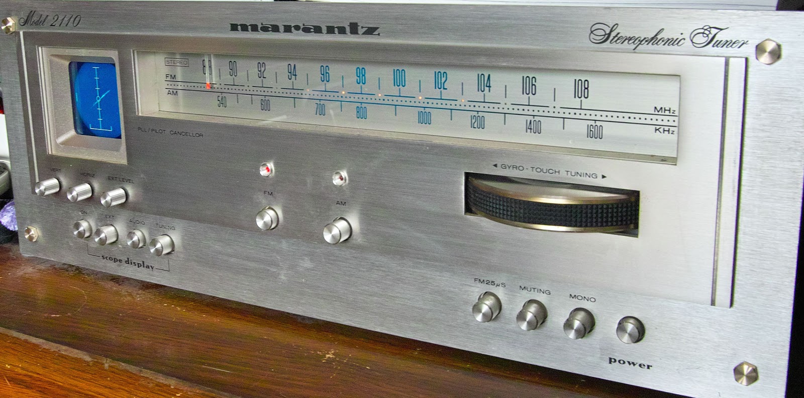
As it turns out I could hear some (admittedly weak) harmonics of a switching supply on my HF receivers, but I generally ignored them until I happened to tune across the AM band on my newly-repaired Marantz receiver (see the previous blog entry) and heard some very strong hum-laden carriers every 30-50 kHz across the broadcast band that blotted out most of the local stations.  Unplugging nearby mains-powered devices soon revealed that the source was (mostly) the power supply pictured above, located only a few feet away from the receiver.

Taking this as a challenge - and an excuse to take some pictures and do a write-up for this blog - I set about to make this power supply much less obnoxious, RF-wise, so I put the power supply on the bench and popped it apart.

Figure 2:
Inside the power supply - the AC input on the left side.
The original bifilar RFI filtering choke (upper-left)
has the green/yellow wire wound onto it.
Click on the image for a larger version.
The usual warnings about high voltages:
  • This power supply - and others like it - operate from potentially lethal line voltages.
  • DO NOT attempt to open or modify a power supply unless you are thoroughly familiar with the proper techniques and safety precautions when working with these voltages.
  • Figure 3:
    A close up of the RFI limiting components.  Below the bifilar
    choke (the device with the green/yellow winding) is the
    capacitor that forces RF energy to be "common mode."
    Click on the image for a larger version.
  • If done improperly, modifications to the power supply may make it unsafe to use and become a fire and/or shock hazard, so do not do this sort of work unless you know exactly what you are doing!
The main RFI suppressing components of the power supply may be seen in figure 4 with the AC input on the left - namely the black device with the green and yellow wire wound on it (a bifilar-wound inductor) and a capacitor - the black rectangular box (marked with "104") below it.

A switching power supply is really a powerful oscillator with the voltage being transferred to the load with a small transformer - the size reduction compared to the old-style "wall warts" being permitted because the power supply operates at a frequency much higher than that of the line voltage's 60 (or 50) Hz, and at several 10's of KHz, usually in the 30-60 kHz range for most of these types of power supplies.  This higher frequency of operation is also the reason why switching power supplies often cause interference issues to radio receivers:  It is the harmonics from this high-power oscillator that are more likely to be conducted to the outside world via the AC power connector and/or the DC output.

In Figure 2 is the diagram of a typical "common mode" AC line filter.  Looking similar to a transformer is the bifilar choke that is doing most of the work of filtering the high frequency components of the switching supply plus it also can do a pretty good job of actually isolating the power line at these higher frequencies so that not only are those spectral components generated inside the power line contained therein, but also that the supply itself won't supply a path to conduct RF energy from whatever it is that is being powered by the supply (a computer, set-top box, modem, etc.) into the power line itself.

The way that this works is that any RF energy on one side of the choke will get coupled to the other side of the choke equally.  Since this bifilar choke is a choke, its inductance will form a series impedance to block higher frequencies from passing through, the effectiveness being related to the inductance of the winding itself.

Key to this working properly is that any RF energy on one side of the bifilar choke must be exactly equal to the other side or else the imbalance can actually cause more interference as unequal RF energy from one side would be induced on the other side.  To force the RF energy to be equal is the job of the two capacitors shown - one on the input, and the other on the output.

This particular power supply had only a capacitor on the load side of the power supply - where the noise was being generated.  While this will do most of the work, it does help to have a capacitor on both sides, but this is often not done as a cost-saving measure.

Figure 4:
Inductance of the original coil.
With only 268 uH per side:
That's not much filtering at
AM or the lower HF bands!
Click on the image
for a larger version.
Since the yellow-green wired inductor didn't seem to be adequate, I removed it from the power supply and measured it (see figure 5).  Noting that the inductance is a mere 268 uH, I thought that I could do better with some other line-filtering inductors that I happened to have in my junk box - this one (figure 6) measuring about 4.594 millihenries (4594 uH) which  is about 17 times as much inductance which also means that it will, ideally, offer 17 times as much impedance to RF energy that might escape from the power supply via the AC power line.

Since the original choke was 268 uH, let's find out how much equivalent series resistance that amount of inductance offers at, say, 1 MHz - in the middle of the AM broadcast band.  The formula for inductive reactance is:

Z = 2 * Pi * F * L

Where:
   F = Frequency in Hz
   L = Inductance in Henries
   Z = Inductive reactance in Ohms

So, plugging 268 uH at 1 MHz into the above we get 1683 ohms - not too bad, actually.  By replacing this choke with the 4.594 millihenry version our impedance scales up proportionally to 28.850k ohms at 1 MHz!  In addition to the bifilar action of the choke, this significant amount of inductive reactance will go a long way toward both keeping the RF energy from the switching supply off the power line, but it will also keep the power supply itself from acting as a pathway to couple potential interference from the devices connected to it to/from the power line.

Comment:

It is common to attempt the use of ferrite beads to suppress RF Interference of this sort, but it's very unlikely that it will help much - particularly at lower frequencies (e.g. lower HF bands such as 160 and 80 meters, not to mention the AM broadcast band) because these devices simply cannot add enough inductance to add a significant amount of impedance:  At these frequencies (say, below 10 MHz) it takes multiple turns on a chunk of ferrite to add enough reactance to make even a small dent in the amount of conducted interference!

Cramming this much larger component into the same space as the original bifilar choke was a bit of a challenge, but laying it on its side and using "flying leads" to connect the inductor to the circuit board made it possible to fit it inside the case.

For good measure I also added another capacitor (a 0.047 uF device) to the "other" side of the inductor (the side opposite the black capacitor mentioned above) to better-equalize any RF currents that might occur across it (the small green capacitor in figure 7).  Just to be safe, I also put some polyimide (a.k.a. Kaptontm) tape on the aluminum heat sink (visible in figure 9) to make sure that the windings of the coil could not touch (and electrify) the heat sink itself or other nearby components.

Figure 5:
Inductance of the new coil.
With 17 times the original
coil's inductance, it's likely
to provide better filtering
at lower frequencies!
Click on the image
for a larger version.
Having installed this new bifilar inductor I still had the original bifilar device (the one with the green and yellow wire) on hand so I decided to put it on the DC output to further contain any RF energy emitted by the power supply - and why not, since it was "free"!  Using its color coded windings, I connected it as shown in figures 7 and 8 with heat shrink tubing to insulate the soldered connections on the power supply's DC output cord.

Putting everything back in the case I carefully re-checked the clearances and insulation to make certain that not only would everything fit, but also that nothing could short out - especially when everything was smashed together when the cover was put back on.  While I could have glued the two halves of the cover back together, I decided to use some of the same polyimide tape mentioned above as it has a very strong adhesive - and I would be able to easily take the power supply apart should there have be a problem.  After reassembly, I then re-checked the DC polarity of the output connector to make sure that I didn't accidentally reverse it when connecting the output choke.

The result?

While I can still "hear" the harmonics radiated from this power supply on the AM radio that's just a few feet away, they were now weaker that most AM stations instead of being "extremely loud" and clobbering much of the AM dial - this fact indicating a reasonable amount of success.  While the intent was not to attempt to completely "clean up" the power supply's spurious radiation, the radical difference indicated that all spurious radiation from this particular power supply was likely to be very much reduced.  Elsewhere in the spectrum, I can no longer hear even a hint of this power supply on any HF band!

Figure 6:
"New" inductor with added 0.047 uF capacitor.  It is
connected with "flying leads" to provide connections
into the circuit.  Not seen in this picture is additional
insulation added between the body of the
new choke and the heat sink.
Click on the image for a larger version.
Since these types of power supplies are seemingly everywhere, it should come as no surprise that there are several of these in my ham shack and I've applied the above techniques to those other power supplies that were found to cause interference on the HF frequencies.  Depending on the power supply and the amount of extra room inside the case, one may (or may not) be able to add as many additional inductors and capacitors as was needed to quash the RFI emitted by the power supply, so in several instances I've added filtering outside the case,  typically inserting capacitors and a bifilar inductor on the DC lead (but close to the power supply) where it would be safe to do so.


Figure 7:
The original bifilar inductor, now connected on the DC
output to provide additional filtering.  Heat-shrink
tubing was used to insulate the output DC connections.
Click on the image for a larger version.
Ideally, one would put such filtering (e.g. inductors) on both the AC and DC leads, but it's worth remembering that these power supplies pollute the RF environment largely by conducting the harmonics of the switching frequencies through the input and output leads:  If one blocks the RF energy from being conducted on just one lead or the other (e.g. the AC input or the DC output) the circulating currents carrying this energy through the power supply (e.g. in on the AC side and out on the DC side) are significantly reduced and adding such blocking can considerably reduce emitted RFI.  Also worth mentioning is the fact that many switching-type DC supplies - particularly "wall-wart" types - have minimal or no common-mode filtering (e.g. using a bifilar choke or two separate series chokes) on their DC output, probably because it's a bit more expensive to do it this way.

I've noticed upon opening the case that some switching power supplies - perhaps of dubious origin and quality - are completely missing the RFI filtering components.  In these same power supplies it is often apparent that there is a position on the circuit board for these components, but they are either empty (in the case of missing capacitors) or jumpered over (in the case of missing inductors) - clearly a cost-saving measure and probably illegal in some countries.  For these power supplies the addition of any RFI suppressing components will likely have a significant effect on reducing interference that they may generate!  I've also observed that many of these same supplies of unknown pedigree often use the cheapest-possible components and it may well be that they will not prove to have a long lifespan!
Figure 8:
The modified power supply with the reconfigured filtering
and placed in the bottom half of the original case.
Click on the image for a larger version

Where does one get these bifilar inductors?  Most computer-type power supplies have these on their inputs and they may be found in most reasonably-quality switching supplies.  Remember how I mentioned that these switching supplies often die after just a couple of years?  These dead supplies may be a ready source of components to better RFI-proof the supply that may be causing interference to you!

Figure 9 shows, in the highlighted portions, the bifilar inductors - and some associated capacitors - found in some typical junked power supplies.  On the left is a typical PC power supply  where one can see what looks like a small transformer next to the AC power line fuse.  On the right is a power supply from a junked VCR with the bifilar inductor also very near the AC power line fuse.

Note:  If you raid junked power supplies for components, make sure that they are unplugged (obviously!) and that the large, high-voltage capacitors filter have been safely dischargedIf you are unsure about how to do this, please seek advice and help from someone who does know before engaging in a project dealing with potentially deadly AC power voltages!

Figure 9: 
Examples of RF filtering components found in junked
switching power supplies.  On the left is a PC (computer)
power supply while on the right is a power supply from
a VCR.
Click on the image for a larger version.
These two bifilar chokes - while somewhat different in style - are split in two with one side of the AC power line on one side, and the other side of the AC power line on the other.  Being wound on a common core, their winding are very tightly AC-coupled (at radio frequencies, at least!) which is how they function to prevent conduction of this energy onto the AC power line.  Before removing them from the board, verify with an ohmmeter from the original AC power connection that the inductors you spot are, in fact, in series with the power line - with one half on one side, and the the other half on the other side!

You'll also notice that these two power supplies have something in common:  There are capacitors very near the bifilar inductor.  In the case of the PC power supply (on the left) there is a large, yellow rectangular capacitor on the AC input of the power supply and on the opposite side, there are two blue disk-ceramic capacitors (one of them covered with heat-shrink tubing).  In the case of the VCR power supply (on the right) you'll see even more filtering:  There are several blue capacitors sprinkled throughout, but also the orange-red capacitors next to the bifilar inductor itself.

It is quite typical for there to be blue capacitors on the inputs of power supplies for filtering - these being "safety components" that are specifically designed for both filtering, and for reliability so that their failure won't inadvertently cause the case of the device to be connected to the dangerous AC line voltage!  The other capacitors - the big yellow one on the PC supply and the two orange-red ones on the VCR supply - actually do much of the filtering.  The one thing that all of these capacitors (blue, yellow and orange-red) have in common is that they are specifically rated to withstand the AC line voltage!  Careful inspection of these components will reveal not only their capacitance value, but also their voltage rating.

If one is reasonably careful, discarded switching power supplies can offer a ready source of components - both inductors and capacitors - to help reduce their conduction of switching energy and the interference that it may cause.

Sunday, November 11, 2012

Resurrecting the 'Scope on the Marantz 2110

A year or so ago I was listening to the radio (yes, I still do that!) and started hearing a buzz and crackle in the audio that sounded "electric."  Since I was listening to FM I thought that this was odd, especially since there didn't seem to be anything around me (a lamp, etc.) that was fizzling out.  Wandering over to the receiver I noticed that the small (2", 5cm) diameter display (a Hitachi 50TB31 CRT, I think) 'scope was fading in and out on the old Marantz 2110 receiver that I was using.
Figure 1:
The Marantz 2110 with the now-functioning scope.
Click on the image for a larger version.

The 2110 is a medium-to-high end FM/AM broadcast receiver from the early/mid 1970's and it is equipped with a small oscilloscope for a tuning aid as much as "ooh's and ahhs."  It had been given to me in a semi-non-working condition by a friend of mine a few years before and all it really needed at the time was a thorough re-alignment and a cleaning of switches and it was back in working order.

In addition to the 'scope having an external X/Y input to set the phasing of external audio gear (e.g. tape recorders, etc.) this receiver will also show two-channel stereo (or mono) audio with the 'scope's X/Y channels being fed by the tuner's own two audio channels:  On mono broadcasts, a diagonal line of varying lengths is displayed, slanting from upper-right to lower-left (as can be seen in the above photo) and with stereo reception one sees a semi-random field of lines with the same general slant:  If, somehow, the phase of one channel were reversed, the slant of the line would also be reversed (top-left to bottom-right.)

For tuning, the 'scope display is a bit different:  On AM, a short horizontal line simply goes up and down, the vertical height being related to the signal strength.  On FM, the horizontal position of a short vertical bar (with respect to the center) represents how well the signal is tuned:  If the small bar is to the left, the tuning dial is low in frequency and vice-versa if it's high.  The vertical position of the small bar also indicates signal strength of FM, but it also indicates something else:  It will show residual AM, and the more of this, the longer this bar will get.

Recall the difference between AM and FM:  On the latter, the signal strength does not change with the audio - or at least it shouldn't!  If it does, this might be a result of one or both of the following:
  • Mistuning of the signal puts a portion of it partway off-frequency.  In that case, as the FM signal wobbles up and down in frequency with audio, part of it may go outside the receiver's filter so less is intercepted, the result being that the signal level as "seen" by the receiver changes.
  • Multi-path distortion.  If there are multiple reflections of a signal due to buildings, mountains, etc. the signal strength of multiple reflections can either reinforce each other or cancel each other out.  As it happens, these effects can be frequency-sensitive and wobbling of the frequency up and down with audio modulation can cause the varying reinforcement/cancellation and also affect the signal strength at the receiver.
Neither of the above two cases are desirable as they represent some sort of signal degradation.  The first one can be a case of mistuning the receiver - or a misalignment of the receiver itself - while the second one can often be remedied by careful antenna placement or adjustment.  This sort of distortion is shown by the changing length of the bar which, ideally it should be a very short vertical line, but if the above distortion occurs, its length and/or height will change with modulation.

So, on FM, the scope is most useful for making sure that the receiver is tuned in the dead center of the received signal - especially important since this receiver doesn't have an AFC - Automatic Frequency Control - to "lock" it on frequency to compensate for the inevitable drift as it warms up.

Back to the 'scope.

But first:

 The obligatory warning about high voltage:

The voltages found in this receiver - particularly those around the mains power supply and the oscilloscope - are potentially lethal!!!  

If you aren't familiar with the safety precautions and techniques related to high voltages
you have NO BUSINESS messing with them!

Before final replacement of the transformer, check the high-voltage capacitors and diodes to make sure that they are in good shape - possibly preemptively replacing them:  It may have been a failure of one of these components that caused the original transformer to fail.  If you are really lucky, one of these components failed and the transformer may be fine!

I can take no responsibility for any damage or injury that might result from anyone attempting to use the techniques described on this page!  While these techniques may be applicable to other tuners/devices with built-in oscilloscopes, you are on your own to do the necessary legwork to determine that device's requirements!
 

When the scope flickered out for good I popped the cover off the receiver and wielding a voltmeter and a somewhat fuzzy copy of the service manual that I'd found online I was chagrined to note that all of the several voltages coming out of the scope's power supply transformer were missing, indicating that the primary winding had failed open:  Unsoldering of the relevant primary wires for the transformer and a subsequent ohmmeter check verified this.

I could have probably come up with some sort of modern switching supply circuit to generate the needed voltage - possibly from a something found on EvilBay - but these sorts of voltage converter modules all have one thing in common:  They produce fairly high amounts of electrical noise at ultrasonic frequencies.  From past experience I knew that if I put one of these devices inside the tuner it would be nearly impossible to keep it from getting into the receiver's other circuits and causing some sort of interference - particularly the AM tuner!  (I don't use the AM tuner much, but still...)

After using the receiver "scopeless" for over a year I decided to see what I could do to effect a replacement so I removed the dead transformer and did a bit of research and found that, as expected, it was a common item to fail and a direct replacement was essentially unobtainable.  In disassembling the transformer far enough to determine that not only had the "inner" connection of the primary winding failed, I also determined that I wasn't going to get the transformer apart far enough to rewind the primary without damaging the other windings.
Figure 2:
A re-drawn portion of the original Marantz's Scope Power Supply Wiring.
The fuses on the power supply board are not shown.
Click on the image for a larger version.

If I wanted the 'scope to work again, I'd need to find a replacement of sorts!

According to the service manual, what I ultimately needed were the following (nominal) DC voltages as best as I could discern from the fuzzy drawing:
  • -601 volts for the CRT's cathode.
  • +186 volts for the vertical and horizontal deflection amplifiers.
  • 6.4 volts AC for the CRT's filament, and this winding had to be isolated so that it could "lifted" to the -601 volt CRT cathode potential.
I knew that it would be very unlikely to find the exact transformer for the 2110, but I figured that using a bit of diode/capacitor sleight-of-hand I could take a single, lower-voltage winding and make various DC voltages out of that:  The main requirement was that the new transformer must have an isolated 6-ish volt AC winding for the CRT's filament!

In looking online at a number of different transformers I ordered a possible replacement from Antique Electronics Supply:  Not an exact replacement, mind you, but one that could have been made to work - but it turns out that I should have looked in my own transformer collection first!

When I looked in my "box o' transformers" I found that I had a several Thordarson T-63041-1CB transformers in my collection that I'd acquired at some point in the unknown past and although I have yet to find official specifications for this device on the web, I also discovered, in the same box with the transformers, a note detailing what I had found several years before when I'd reverse-engineered it using an ohmmeter to determine the likely windings and then the careful application of AC voltages through a "Variac" (tm) type autotransformer.  Based on what few specifications were on the transformer's label (e.g. its primary voltages) I was able to figure how to safely apply power to its primaries (it has two!) and then measure the secondary voltages.  As it so happens it had not only an isolated secondary that measured 6.6 volts (unloaded!) but also one that measured 180 volts.

Figuring that I could make something of this transformer, I set to work!
Figure 3:
The transformer used as a "replacement".  Most
importantly, it has an isolated 6-ish volt filament winding!
Click on the image for a larger version.

This transformer was slightly smaller in height and width than the original, and a millimeter or so "thicker" but it looked as though I could cram it in the original transformer's metal casing.

First, I drilled a hole one of the original transformer's side (called the "bell") covers (and filed it to smooth the sharp edges) to allow access to the secondary winding's wires as this transformer had wires coming out of both sides of the winding face instead of the front and back as per the original.  I then centered the transformer in the original side covers and was able to "gently force" the transformer into the U-shaped mounting bracket after bending it to accommodate the slightly thicker transformer.  Holding everything in a vise, I was able to attach the bottom cover and bend the original cover's tabs into place, using a screwdriver to align them and when I was done, the "new" transformer didn't look much different from the original!  Using the original case - and its implied shielding - is often important as it prevents the magnetic field from the transformer from affecting the trace of the oscilloscope!

Now, to make both +186 volts and -601 volts out of a single 180 volt winding!

As we can see from the drawing in figure 2, individual windings - all referenced from the center-tap - were used on the original transformer to produce the high voltages.  In this case, a pair of 166 volt windings, center-tapped, were used to full-wave rectify and produce the nominal +186 volt DC supply for the scope's deflection circuits.  On one side of the center tap we also see a 430 volt winding that was half-wave rectified to produce the -601 volt which was then filtered by a series pair of 10uF, 350 volt capacitors - and this voltage was applied to the floating 6.4 volt filament windings.
Figure 4:
The diagram of a diode-capacitor tripler to increase the voltage of a
180 volt AC winding to produce the negative CRT Cathode voltage.
The two capacitors on the left can be 1uF at 450 volts - enough for
the low-current CRT beam supply.  The diodes are 1N4007 types.
The capacitor on the right is representative a capacitor in the original circuit.
Click on the image for a larger version.

Fortunately, there's nothing here that overly complicates the ability to generate these same voltages via an alternate means, and as it turns out we can use our new-found transformer's 180 volt winding to generate both of these these voltages.  Generating the +186 volt supply is trivial:  Simply ground one end of the 180 volt winding and half-wave rectify it - and this produces roughly +180 volts DC, just what we need!  See figure 5.

Generating the -601 volt supply is a bit trickier - but not overly so:  By using a small assortment of capacitors and diodes we can take that 180 volt AC waveform and multiply it several times to produce the desired voltage.  In this case, we use a voltage "tripler" which takes advantage of the peak voltage of the 180 volt winding so that the actual "AC-Input to DC-output" voltage ratio is closer to 3.8 than 3 and this just happens to yield a voltage very close to our nominal -601 volts, or around -615 volts (under circuit load) as depicted in the drawing above.  To our advantage, we need very little current to supply the CRT's cathode which allows us to use rather small-value (1 uF) capacitors as depicted below.

As it happens, some of the circuitry required for a tripler is already included in the original Marantz power supply, namely the last diode and capacitor on the far right of figure 4 and this means that we don't need to build all of the circuity above (but if we did, it wouldn't hurt...) so we end up with the final schematic shown in figure 5.
Figure 5:
Alternate power supply for the Marantz scope.  The portion in the box
is the "external" diodes and capacitors that we will mount in heat-shrink
tubing and connect to the Marantz power supply board.
Note that the "ground" inside the box also connects to J816.
Click on the image for a larger version.

As seen in the drawing the filament supply connects to J819/J820 in the same manner as the original since we have the same "floating filament" winding arrangement as the original transformer.  We don't have a center-tapped transformer, so we simply connect one end of the 180 volt winding to the system ground (J816) while the other end of the transformer connects to either J815 or J817 (or both, if you really want)  but it doesn't matter which, since we are using a half-wave rectified circuit instead of the original center-tapped full-wave!

Even though our new transformer's winding produces 180 volts AC instead the 166 volts AC of the original, our DC voltage is ultimately about the same due to the half-wave rectification.  Our power supply is still "clean enough" in terms of AC ripple since the capacitance on the original power supply board (10uF) is more than adequate.

Figure 6:
The added circuit, consisting of two
1uF/450 volt capacitors and two
1N4007 diodes is shown connected,
floating in space on their connecting
wires before being
enclosed in heat-shrink tubing.
Click on the image for a larger version.
What we need to complete the power supply is to construct a simple module consisting of the components within the box in figure 5 and as can be seen, this is simply two diodes and two capacitors.  What you might notice is that some of the circuity appears to be missing when compared with drawing in figure 4, but recall mention of the fact that on the original circuit board we have a diode and capacitor already present as shown in figure 2 so we can leave those parts out!

In figure 6 we can see these components assembled, hanging in free space on the wires - along with insulating tubing on the component leads - connected into the circuit.  If you look carefully at both the picture and the drawing above you'll note that it connects in only three places:
  • The "ground" (bottom of the capacitor in the box) goes to J816 - the main system ground..
  • The "input" (180 volts AC) goes to J815 and/or J817 - the same terminal that the "top" of the 180 volt winding was connected.
  • The "output" of the circuit connects to J818 where the original 430 volt winding connected.
This circuit works perfectly!

I measured about +175 volts where +186 volts should have been (close enough!) and -617 volts where -601 volts was to be (pin 1 or 2 of J914).  It's worth mentioning that if you measure the voltage at J818, you won't see the -600-ish volts since the rest of the multiplier circuit (e.g. the last diode and capacitor) is on the board, which is why you'll see the -600-ish volts only at J914!  Carefully measuring the filament voltage (which is at -600 volts with respect to the chassis!) I observed 6.3 volts or so - a slight drop from the "unloaded" 6.6 volts measured above and just perfect for the CRT filament!

To complete the circuit I added a bit of extra insulation to some of the wires connecting the capacitors and diodes (I used some craft paper, taped together) so that they could not touch when the piece of heat shrink tubing that was slid over the above was shrunk, compressing components and leads together.  Finally, the module was completely enclosed in shrink tubing and attached to the brown wire from J914 with a single nylon wire tie to keep it in place as can be seen in figure 6.

Taking my own advice, I also checked the two 10 uF, 350 volt series-connected capacitors that filtered the -601 volt supply.  When powering up, I (carefully) measured the voltage across each capacitor and while half the power supply voltage should have been across each capacitor, I noticed that there was about 400 volts across one and 200 volts across the other indicating that at least one of them had a problem!  Unsoldering them from the board (after first having disconnected the power and shorting them out to discharge the remaining voltage!) I noticed a small amount of crust on the board as well as some corrosion around the capacitors' leads indicating that they were leaking electrolyte.
Figure 6:
The circuit in heat-shrink tubing, installed.  The "new" transformer is the one in the background, on the left.  If you look carefully you can see the new hole where the secondary's wires emerge.  Using the original transformer's case, it was nearly a perfect fit!
Click on the image for a larger version.

After replacing them with a pair of 33uF, 400 volt units I saw that the voltages across each capacitor were within 10-20 volts of each other.  Practically speaking, a capacitor value as low as 1 uF would probably suffice, but all I had in that voltage range were the 33uF units mentioned.  These two capacitors, when replaced, should be identical and from the same batch, if possible.  Normally, high-resistance (330k-680k) resistors are placed across series-connected capacitors to equalize the voltage, but that was not done in this case:  Next time I have the receiver apart I will add those to the bottom of the board - just to be safe!

Running the receiver for several hours I observed that the transformer doesn't get any warmer than the ambient temperature within the receiver itself.  I seem to recall that the original transformer ran a bit warm indicating that it was either already somewhat faulty or, more likely, that it had originally been under-designed with too-few turns on its primary and causing it to run a bit warm (a cost-savings measure, no doubt!) and possibly leading to its ultimate failure.


Thursday, October 18, 2012

Smoke and flames from my IFR-1000S...

I'd not really intended to have two posts in a row about repairing service monitors, but fate/opportunity intervened...

Figure 1:
The gray, charred stump of the failed tantalum capacitor in the center
of the image, just above the potentiometer shaft.)  The original,
nylon extension shaft broke several years ago and here, it is
shown having been mended with two overlapping
layers of heat-shrink tubing.
Click on the image for a larger version. 
The other night I had a few minutes to spare and I decided to take a quick look at my old IFR-1000S service monitor:  I'd remembered that the last time I dragged it to a repeater site there was something about it that was flaky - but I couldn't remember what - the 'scope, I thought...

So, I plugged it in, turned it on and everything was fine until I flipped the switch to apply power to the 'scope.  At this point the front panel lights dimmed momentarily, following by a loud bang (even though it was muffled by the unit's metal case) and smoke billowed out from every gap in the front panel along with a bright, flickering yellow light from a fiercely burning flame within.

Of course, I turned it off and fortunately, the flame quickly died out!

Hmmm...

Undoing about a dozen screws I soon had the cover off and discovered the culprit:  A dipped tantalum capacitor (150uF, 15 volts) on the the high voltage power supply board for the oscilloscope had incinerated itself.  Fortunately, aside from leaving a sticky, smoky residue on the nearby components, adjacent chassis panels and the inside of the wrap-around case, there didn't appear to be any real damage.

I should say that once I saw what had "flamed out" I wasn't too surprised:  Dipped tantalum capacitors don't fail too often, but when they do, they usually fail spectacularly, often burning holes in the circuit board and destroying nearby components!

Figure 2:
Inside the wrap-around cover - evidence of smoke and flames!
Click on the image for a larger version.
Grabbing the service manual I quickly located the faulty capacitor on the schematic diagram and noted that it wasn't anything too critical - a bypass capacitor on the power supply to filter the ripple from the 'scopes high voltage power supply (essentially an oscillator) from the main 12 volt power bus - this, to keep "noise" from getting into other circuits.

Carefully unsoldering the remnants of the capacitor (now a small chunk of charred tantalum) I shook out the other pieces of the capacitor that had fallen inside the unit and the powered it up.

Everything looked good!

Now, to replace the capacitor.  The original was a dipped tantalum unit, this type chosen because of its low ESR (Equivalent Series Resistance) and its ability to effectively filter the high-frequency noise produced by the high voltage inverter.  For this task I wasn't going use an "ordinary", cheap capacitor since its filtering ability may be somewhat diminished at the frequencies involved - around 20 kHz.

Back when the unit was made the best capacitors for high-frequency filtering were tantalum units or specially-made low-ESR electrolytics, but the latter weren't extremely common.  These days, with the proliferation of switching power supplies it's quite common to find high-performance, low-ESR electrolytics designed for just this task so I rummaged around and found a 330uF, low-ESR 105C (high temperature) capacitor that appeared to be well-suited for the task.

Figure 3:
The new (blue) CDE 330uF low-ESR electrolytic.
Click on the image for a larger version.
While it would have been ideal to have completely pulled the circuit board to install the replacement capacitor, I knew this to be a chore - having done it several times before - so I was able to do a careful "top soldering" job, heating the component's through-hole vias from the component side of the board.  Not having pulled the board out of the unit also meant that some of the sticky, smoky residue remained in some of the inner recesses and on some of the adjacent components, but I was content to clean off what I could reach using denatured alcohol.

The upshot?

The unit is now working again and the new capacitor seems to be doing its job.  If I have a reason to do so in the future, I'll pull the scope module go through it to remove the last traces of the smoky residue and, perhaps, preemptively replacing the other tantalum, but for now...

I still don't remember for certain the problem for which I was checking out the service monitor!

Additional random comments:

A few months later (8/13) I noticed that sometimes the IFR-1000S would hum when it was powered up - but not always.  Clearly 120 Hz ripple, it was pervasive enough that it would register as 200-300 Hz of deviation on an otherwise unmodulated carrier, appearing as a "dirty" waveform on the output signal as well as being visible on the scope and audible via the speaker.

Taking the cover off, the hum stopped, but I checked the filter capacitors in the power supply (some of which I'd replaced a few years ago) and found them to be good.  After having used it a few more times hum-free, the problem appeared again and this time I happened to notice, as I was picking it up while it was powered on, that the hum changed.  Pushing on the case and wiggling things I discovered that the hum changed radically when I wiggled them main AC power connector - "Jones" plug.

Upon disassembling the unit I saw that the solder joints on the connector were just fine, but that the Battery - lead from this connector (which can be used to operate the unit from DC power) shared a heavy black lead that came from the main power supply, bonding it to the chassis.

Hmmm...

Grabbing a screwdriver, I immediately noticed that this screw was a bit loose.  As it turned out it was this connection that was getting flaky, developing a slight amount of resistance.  Since it came from the power supply this caused the regulation (and consequently, ripple rejection) to suffer.  I put a drop of anti oxidant grease on the connections and properly tightened the screw, thus fixing the problem!

Friday, October 5, 2012

Resurrecting a CE-50A service monitor

Several weeks ago a friend of mine gave me his old Cushman CE-50A service monitor - a "Swiss army knife" piece of test equipment used for testing and evaluating 2-way radios, receivers and transmitters over the range 0.1 MHz to just under 1 GHz with the capability of testing receiver sensitivity, transmitter modulation and transmit power - all of this in addition to being a general-purpose audio and RF signal generator and low-end, general-purpose oscilloscope.  He'd had this unit for about a decade and had bought it in a non-working condition, having gotten it functional and had used it many times for radio maintenance.  His needs had changed and he no longer had the time and equipment to repair it so he figured that if he needed a piece of test equipment with the necessary functionality, he knew plenty of people (such as me!) from whom he could borrow the necessary gear.

Figure 1:
The now-working CE-50A with it's scope showing an "O'clock" - an
oscilloscope-based chronometer - just for fun!
Its display is slightly distorted due to my failure to compensate the
scope leads!
Click on the image for a larger version. 
Some time in the past year or so it quit working properly.  For a long time the front panel BNC connector from which the signal generator output - and the wattmeter was input - was flaky.  While a nuisance, it was still workable - at least until the built-in wattmeter quit working due to the internal RF relay not being triggered by RF any more.

Fixing the scope:

So, it fell into my hands along with the service manual.  Upon turning it on one of the first things that I noticed was that while the oscilloscope CRT was fairly dim, all displayed traces - from any source - had some "fuzz" on them at a frequency that was in the 20 kHz or so range.  My first inclination was that I should "shotgun" (e.g. replace) all of the electrolytic capacitors in the main power supply.

I should have gone with that first inclination.

I then thought that, perhaps, the scope's power supply board had lost some capacitors since not only did it supply the high voltage for the CRT, but it also generated other voltages (e.g. 90 volts for deflection and a negative voltage for other scope-related circuits) so I replaced all of the electrolytics on that board.

No change.

Poking around I then noticed that the high voltage was around -950 volts instead of, as indicated by the manual, -1400 volts.  Pulling the high voltage converter board again I realized that it didn't match the one in the book, being a different part number and further scrutiny revealed that about the only difference between the board and the one depicted in the book was that it was supposed to have a 3-stage high-voltage multiplier rather than just a 2-stage.  Rummaging around, I found some high-voltage 0.01uF disk ceramic capacitors and some 6000 volt, low-current diodes and constructed the extra stage, bringing up the high voltage to more-or-less what it should be.

This made the scope trace significantly brighter - as well as narrower and shorter.  Expectedly, the higher cathode voltage on the CRT increased the velocity of the electrons which meant that they were more difficult to deflect and this required that I re-tweak the vertical and horizontal amplifiers to get it back into calibration.  While doing this I couldn't help but notice that the service manual was obviously incomplete on some points, namely leaving out the descriptions and adjustment procedures for entire circuits within the vertical and horizontal deflection requiring a bit of on-the-spot decipherment of the apparent intent of the designers.  After a bit of tweaking, I got the scope back into calibration.  Even after all of this, the "fuzz" on the scope was still there - although slightly diminished - probably due to the increase in acceleration voltage.

RF power/signal generator transfer relay:

Setting aside the fuzz on the scope for the time being I attacked the problem with the internal relay.  Normally, the "Signal Output" jack is connected to the antenna input of a receiver under test and is used to apply a variable signal level used to test the radio's performance and as a signal source to aid adjustment.  When one transmitted into this same port an internal relay was supposed to switch the signal path from the output of the signal generator and connect it to the internal power meter, allowing one to measure transmitter power from less than 1 watt to 100 watts.

Except that it didn't, and that was the problem.

Of course, the module with this relay was the most deeply-buried circuit within the entire unit.

Getting access to this module required the un-mounting and disconnecting of several modules before its nearly two-dozen screws could be accessed and the cover removed.  Having just enough wires still connected to do so, I was able to transmit some RF power into the unit and saw that an 8 volt supply that fed nothing but that power detect circuit and its relay was going from its normal 8 volts down to 3 or so under load.  Referring to the manual I then noticed - with some annoyance - that this same 8 volt supply was now buried under the modules that I had to flip open to access this circuit to take the measurement, so I had to put everything back together.

Finding the 8 volt power source - a simple 7808 3-terminal regulator bolted to the chassis near the rear of the unit - I was immediately struck by the fact that its input voltage was varying between 60 and 70 volts.  Looking at the schematic I could see that its power source was either the main 12 volt bus from the power supply, or from the battery input - the choice between the two selected automatically with a pair of diodes in "diode-OR" configuration.  Putting the voltmeter on the source voltage I determined that yes, the 12 volt supply was correct, but the battery supply - which should have been at about 14 volts for charging the not-installed battery, was in the 18-20 volt area.

This last point was definitely wrong, but where was the 60-70 volts coming from?

Grabbing an oscilloscope I noticed, in looking at the battery charge line, that it was very "dirty" with 70-80 volt spikes on it which were then being rectified and filtered by the input diode and bypass capacitor on the 7808 which was apparently shutting down under even a very light load.

It was now that I finally "shotgunned" the capacitors in the power supply and in so-doing, I found that it was in the charging circuit for the battery that a capacitor or two had failed and because because of this, the circuit had gone into oscillation and was the source of the spikes.

I really should have replaced all of the capacitors in the power supply when I started!

Finding and replacing every electrolytic capacitor on this board (nearly all of them were found to be well out of spec!) I re-installed it and observed that the input of the 7808 was now in the 13-15 volt range and that the RF relay now operated normally - and also that the "fuzz" in the scope was completely gone!  Interestingly - but not too surprisingly - the scope now appeared to be even  "brighter" than it had been before owing to the fact that without the "fuzz" to fatten all of the lines, they were now fairly narrow and crisp, giving the illusion of additional brightness.

Using a handie-talkie I fed power into the jack and observed that I was now getting a wattmeter reading - but something was still wrong:  It read very low.  Further investigation showed that the meter reading seemed to change slightly every time it was activated, indicating a mechanical problem somewhere and even more revealing, I was getting a much higher and "less incorrect" reading when transmitting at 440 MHz than I was at 145 MHz indicating an "air gap" somewhere in the signal path with capacitive coupling across it.

At this point I connected the handie-talkie to the input side of the 20 dB, 100 watt attenuator inside the unit - a point "after" the relay - and observed that  the readings were closer to being correct and consistent both from one reading to another and over frequency, being fairly consistent between VHF and UHF andpositively indicating that the problem was likely inside the module that I'd previously taken apart - and mostly likely the RF relay.

This meant tearing the unit completely apart... again... and possibly replacing the RF relay.  Fortunately, Cushman had chosen a rather common component for this - a small Switchcraft RF relay that had been used in land-mobile gear in the 60's and 70's and a type of which I had some spares that had been pulled from scrapped gear.  While the relay itself was identical, the coil was different but inspection showed that it should be possible to drill out the rivets - leaving the posts - and then epoxy the old coil onto the "new" relay were it necessary to do so.

I carefully unsoldered and removed the relay and took off its cover to inspect its insides.  This relay is fairly simple - see figure 2 - an armature inside a milled-out channel (for RF impedance matching) with a pair of contacts at the far end with a plastic button transferring the motion from the armature on the coil.  What I noticed was that the armature was out of alignment, touching the other contact with only a "glancing" blow and thus explaining why it wasn't working properly.

Figure 2:
The guts of the same type relay used in the CE-50 and a potentialreplacement!  The problem with the original relay was
where it emerged from the coax and into the body of the relay (on the right) and connected to the armature:  It seems that
during the original installation the polyethylene insulation melted and allowed the armature and contacts to move out of
alignment, eventually causing the relay to become unreliable.
Click on the image for a larger version.
These types of relays were originally made with short length of coaxial cable crimped onto their ends and apparently the manufacturer of the service monitor (Cushman) had simply cut off the polyethylene dielectric coax, leaving a short portion of the center conductor to be soldered into the circuit.  What had apparently happened was that upon installation, a bit too much heat had been applied while soldering and the plastic dielectric had melted, causing the armature had moved out of position.

Using a pair of needle nose and carefully applying heat to re-soften the plastic I carefully repositioned the armature into proper alignment and then, to make sure that his wouldn't happen again, encapsulated the end of the armature (the far-right end in figure 2 where it would connect to the coaxial cable) in a small amount of clear epoxy to provide a more rigid substrate than the polyethylene had provided.  After the epoxy cured I took this opportunity to inspect the relay contacts more closely - which appeared to be nearly pristine - and then burnished them with a piece of scrap paper to remove any surface oxide that might have formed.  I then put a drop of "Stabilant 22" - a synthetic contact enhancer and anti-oxidant - on the relay contacts to assure continued operation.  Finally, I very carefully bent the armature itself so that its "springiness" would be modified to more positively and forcefully make contact.  After all of this, I reassembled the relay, installed it into the circuit and tested it.

It worked!

Putting everything back together I went about recalibrating the wattmeter and found that as with the section that described the 'scope, the service manual was woefully incomplete requiring that I reverse-engineer their original intent, invent, and perform the calibration procedure - and then note it in the manual for future reference!

Why doesn't the PFM-Generate mode work?

At this point everything seemed to be working so I went about checking and recalibrating the various sub-instruments as required - until I came across the need to check and calibrate the "PFM Generate" function.  As it turns out, in addition to AM and FM, there's a "PFM" (presumably meaning "Pulse FM") mode that isn't well described in the manual.  When set to its equivalent in the "monitor" (receive) mode, this seems to insert a low-pass filter into the demodulator path to remove high-frequency noise, but when set to "generate" mode, the PFM setting seemed to do nothing at all except generate a CW (dead) carrier.

Again, I tore into the unit and with the aid of the manual I started tracing the signal path of the front panel selector switch and found that it was getting everywhere it should have.  I finally got to the audio board where these signals were routed and noticed that when in PFM, the audio path went through a separate adjustment and audio switch just for the PFM mode - and it seemed to be working.  Moving to the next circuit earlier in the audio path I found an audio gate transistor that seemed to be disabled in PFM mode with a diode.  At this point I went back and reviewed the manual's circuit description and interestingly, it described in some detail the audio paths for all modes - including PFM - but then, in a separate paragraph it mentioned in passing that this particular diode was there to disable the audio in the PFM mode!  Why, then, was there extra circuity for the PFM mode if it was ultimately disabled?  At least this answered the question and told me that "PFM-Generate" was supposed to do nothing!  While I could easily remove the diode and make this mode functional, I decided to leave it alone for now.

Comment:
Further testing and "reading between the lines" of the manual it would appear that the "PFM" mode is intended only for modulation applied through the "External Modulation" input jack - a point that the manual doesn't make clear.  Since external modulation is, in fact, possible in the other modes, it is unknown why that would have yet another switch position to accomplish this!

Hummm...

While chasing out the PFM-Generate mode I noticed a small amount of hum coming from the speaker.  In checking the 12 volt supply I could see that there was about 35 millivolts of ripple on it, so apart came the power supply again.  This time, I traced the 120 Hz ripple to the switcher board and then noticed that a previous modification had been done to it where an output filter capacitor had been installed with a series resistor - presumably to reduce inrush current - replacing a smaller-value capacitor that the diagram had showed as being located directly across the switcher supply's output.  Putting a scope there showed that there was a few hundred millivolts of ripple at the switching frequency (25 kHz or so) but that this was being filtered out by a later power supply stage - the one on which I'd shotgunned all the capacitors.  Using a low-ESR capacitor specifically designed for switching supplies, I reinstalled the device that had been missing and not only did the switching frequency ripple decrease significantly, but the 120 Hz ripple on the 12 volt supply went down to the 10-12 millivolt area (which was quite acceptable) - but the hum in the speaker, being much lower, was still audible.

Turning my attention to the audio amplifier I noticed that the speaker had been coupled to the output in an odd way.  This amplifier was a fairly simple, transistor-based circuit using a pair complimentary transistors in the output to the capacitively-coupled speaker.  Typically, the speaker coupling capacitor is connected between the output of the "totem-pole" transistors and the speaker, but in this case, the DC blocking/coupling caps were on the "low" side of the speaker - and there were two of them:  One between the speaker "low" side and ground and another between the +12 volt line and the speaker "low" side - and it was this latter capacitor that appeared to be coupling the power supply hum into the speaker.  I'm not sure why they did it this way, but my guess is that it prevents a loud "pop" in the speaker when the power is turned on and off, so I left it this way, deciding that the hum wasn't that bad anyway...

Front-panel connector:

The final item was to address the problem with the front-panel RF connector.  As often happens with BNC and N-type female connectors, the "leaves" on the springy center connector weaken and break off - and that had happened to the previous owner.  Unfortunately, a rather specialized chassis-mount BNC connector had been used on the end of small-diameter PTFE hardline coaxial cable.  For trouble-shooting purposes, the previous owner temporarily connected a male BNC connector via a length of cable, but now that I'd gotten the unit back together and fully functional I wanted to make a permanent fix.
Figure 3:
In Tracking Generator mode, testing a 10.7 MHz ceramic filter.  Because the
filter was fed/sourced with 50 ohms instead of 330 ohms, there's extra
passband ripple!
Click on the image for a larger version.

In rummaging around the junk box I found plenty of crimp-type BNC chassis-mount male connectors that would fit in a 1/2" diameter hole - but the one on the unit was a 3/8" hole with a flat spot and I wanted to avoid - if possible - drilling it out.  What's more, I didn't want to use a standard chassis-mount solder-on BNC connector as this RF connection had to be both RF tight and fairly impedance "flat" from essentially DC to 1 GHz - difficult to do with a solder-on connector.  Finally, I found one 3/8" O.D. chassis-mount female BNC connector with a coaxial crimp fitting it to RG-174 sized PTFE flexible coax so I carefully disassembled it and managed to successfully attach it - with a bit of soldering - to the small-diameter hardline inside the unit.  A bit of testing showed that it worked nicely over the entire frequency range, so the unit was reassembled and the project was considered to be complete!

Comment:  I later noted that the exact replacement connector was available via Pasternack Enterprises for somewhere around $50 - something to keep in mind should this repair fail at some point.

Conclusion:

Overall, the repair was a fun project, taking me several places that I didn't anticipate going and reminding me, again, of that old adage: 
"When in doubt, check the power supply!"

Additional comments:

More recently (8/13) I had a strange problem occur:  When in the spectrum analyzer mode the synthesizer lock would come and go while the frequency offset meter would slowly drift up and down.  Apparently, something was slightly unstable, preventing the main PLL from locking.

In trying to troubleshoot this I looked at some of the plug-in boards and noticed that a lot of the 100uF, 16 volt capacitors were starting to leak - and there are a couple dozen of these scattered throughout the unit on most (if not all) plug-in boards that are used as power supply bypass/filter capacitors.  While no damage seemed to have been done other than a slight amount of surface corrosion that was easily removed, I did replace pretty much all of them and at some point the problem with the synthesizer's locking went away - although I don't know for certain on which board the "fix" occurred - or if it somehow fixed itself with my re-seating the boards.

Anyway, it would be a very good idea to take a close look at all of the 100uF capacitors (and other electrolytics, as well) on the various boards and replace them as they are probably starting to leak on your CE-50, too!

Tuesday, September 18, 2012

Throwing one's voice 95 miles on a lightbeam

For more information about long-distance optical communications, go to the modulatedlight.org web page  (link)


This past weekend (September 15-16, 2012) was the 2nd part of the annual ARRL 10 GHz and up contest and we decided to use one of the highest-available amateur bands - the one known in the FCC rules as "275 GHz and up."  Actually, this covers a lot of territory including submillimeter radio frequencies and far infrared wavelengths, but the part that we are more interested in is that for which most of us are equipped to detect directly - light.

We've done this before, managing to have spanned 107 miles (173 km) on several occasions and even 173 miles (278 km) (read about those efforts here - link) so we weren't going to break any of our own DX (distance) records, but it's fun to do this, anyway - and it gave us an excuse (as if we really needed one...) to go out and test some new gear that had not yet been tested over anything but relatively short (20 km or so) paths.

The two locations for the stations were about 96 miles (154 km) apart with Ron and Elaine Jones (K7RJ and N7BDZ) being at the far end at an elevation of about 5600 ft (1700 m) ASL near Park Valley, Utah in the extreme northwestern corner of Utah, a few miles from where the U.S. Transcontinental Railroad was joined for the first time in 1869 and only a few hundred meters away from the historic stagecoach route that paralleled part of that later railroad.  Along with friends Gordon (K7HFV) and Gary (AB1IP), I  was closer to home at about 9300 feet (2830 m) near a minor protuberance known as "Bountiful Peak" about 10 miles (16 km) north of Salt Lake City.  As it turns out, the path is a grazing one and were it not for the slight refraction of the Earth's atmosphere, it may not even quite be "line of sight."

We'd tried this same path during the first weekend of the 10 GHz and up contest but the thick veil of smoke from wild fires elsewhere in the western U.S. prevented a successful contact - although our light beam was occasionally just visible to the binocular-aided eye in Park Valley.  This time, however, the air was reasonably clear, only somewhat hazy from the still-burning fires:  Since we "almost" made contact a month ago we were confident that this time we would have no problems.
Figure 1:
The high-power red LED shining to the north-northwest.
The lights of Layton, Utah and surrounding communities
may be seen way below, in the background! The dot at the terminus
of the red shaft of light is the light from Ron's end of the path.
Click on the image for a larger version.


Soon after we arrived on site Ron shone a 500,000 candlepower halogen spotlight in our direction and immediately we noted a lone, flickering, yellow-red dot in the blackness "above" the last ribbon of visible lights from the populated areas of Layton and Ogden about a mile (1600 meters) in elevation below us.  Using this as a visual reference I swung my high-power LED in his direction, using the Rayleigh-scattered shaft of red light as a guide, and immediately Ron reported that it was easily the brightest light visible:  Considering that there were only a small handful of lights visible from his dark, rural location, anyway, this wasn't saying much, but if anyone where to have dropped by and looked in that direction they would have seen the bright, red light and asked, unprompted, "What's that?!?"

Using our light as a guide Ron immediately fine-tuned his pointing and soon, a very obvious red light appeared in the darkness.  Initially starting out with the lower power 3-watt LED he soon switched to the much higher-powered 20-30-ish watt LED and the red dot in the distance was even more striking than before.  The dot at the end of the red shaft of light in the above picture was from Ron's LED.

Soon after we brought our transmitters up to full power we reduced them again to 1/4-1/15th as each other's signals were strong enough that there was noticeable distortion in the received audio - and it also allowed us to run full-duplex (e.g. both sides being able to send and receive simultaneously) without intercepting as much of our own, scattered transmit light and causing acoustic feedback between our speaker and microphone.

This was the first actual "long distance" test of the Phlatlight-based optical transmitter - these using CBT-54 LEDs and permitting a 20dB improvement on the audio received at the far end.  This also was the first test of some APD (Avalanche PhotoDiode) based optical receivers that I'd built some time ago (see the link at the bottom of the page) so we set about reduce each other's LED currents to do a sort of "limbo" dance - that's to say we wanted to answer the question "How low can we go?"

It immediately became apparent that even though we could read the Phlatlight modulators' current with a resolution of 0.1 amp, this was still too coarse when we got down to the lowest readable current and were still able to hear each other, so Ron switched to the older 3 watt Luxeon on which the LED current could be measured and adjusted down to the single digits of milliamps.  As it turned out, speech was copyable - with some difficulty - down to the 40-50 milliamp range with the old receivers but the APD receivers extended this down to around 20 milliamps - an approximately 6-10dB improvement, a number that agreed reasonably well with what had been calculated using similar measurements done at home on my "Photon Range" using a very dim LED and test receivers.

Practically speaking this meant that at full power with the Phlatlight LEDs we had about 50dB of  excess signal at the output of the receivers as compared to the minimum possible signal level using baseband speech and the "naked" ear.  Switching to MCW (tone-modulated Morse code) we could extend this by another 6-10dB and the the use of narrowband digital signalling techniques (such as WSPR or QRSS CW - very slow Morse) could have extended this by even another 20 dB or so.  The implication of this is that, in theory, we could communicate over that distance with only a milliamp or two of LED current!
Figure 2:
This time, a high-power green LED!
Click on the image for a larger version.

Satisfied with our tests I switched to a green CBT-54.  Interestingly - but not too surprisingly - Ron reported that subjectively the green LED wasn't really any brighter than the red had been.  On previous tests at much shorter distances (a few 10's of miles/km) the green far outshone the red owing to the fact that the human eye is at least 5 times as sensitive to green than the wavelength of red LED that we were using.  For these distances the atmospheric attenuation was sapping the vast majority of our light since the shorter (green) wavelengths are attenuated at a far higher rate than the longer ones, a fact that explains red sunsets and that we observed, at the beginning of our testing, that his white, halogen spotlight appeared to us as distinctly yellow/red in color.

The silicon photodetector didn't fare any better since it had far less sensitivity at green than red, the two factors (atmospheric and the Si sensitivity) adding up to between 20 and 30dB in degradation - assuming that the subjective measurement of "equal" brightness between red and green was correct.  As it turns out the degradation was probably far greater than that as the APD-based receiver could hardly detect voice at all, but this may have been also due, in part, to the fact that the gain of a standard APD drops off precipitously with shorter wavelengths and that it was likely not focused properly for green light due to chromatic aberration of the Fresnel lens!  In retrospect we should have switched to a receiver with a larger, "non-APD" detector - and thus less sensitive to misfocusing due to chromatic aberration.

In addition to using high-power LEDs, we also exchanged 2-way communications using plain, ordinary, cheap low-power red LED laser pointers.  The signals were far weaker - mostly owing to the lower optical power of the laser pointer - but each other's lasers were visible to the naked eye over the distance.  Because of the combination of the laser's (relatively) coherent light and its small exit aperture (small beam diameter) the scintillation (fading) on the laser-based link was terrible while on the LED-based link it was only just noticeable.  Some of the methods and techniques to communicate using laser pointers may be found in the September 5th entry of this blog.

After several hours of standing around in the dark on the mountain, we decided that it was getting early (approaching 2 AM!) and packed things up and made our way down the mountain.

Overall, it was a fun little jaunt giving us a healthy dose of nerdiness... enough to last for a few weeks, anyway!

Afterward:
While we run these tests, we'll often play something from portable audio players so that we have a continuous source of sound.  In this case, one of the audio sources that I used was from a Soldersmoke podcast.
For the heck of it, I emailed Bill, N2CQR, who produces this podcast and he put it on his blog page (link) as well as commenting on it in his next Soldersmoke podcast (link)!  This may have had something to do with this post appearing on Hack-A-Day (link)!


Links from the "Modulated Light" (link) web site:
Be sure to check out the "ModulatedLight.org" web site's other pages as well!

[End]

This page stolen from ka7oei.blogspot.com